Frequently Asked Questions (FAQ)
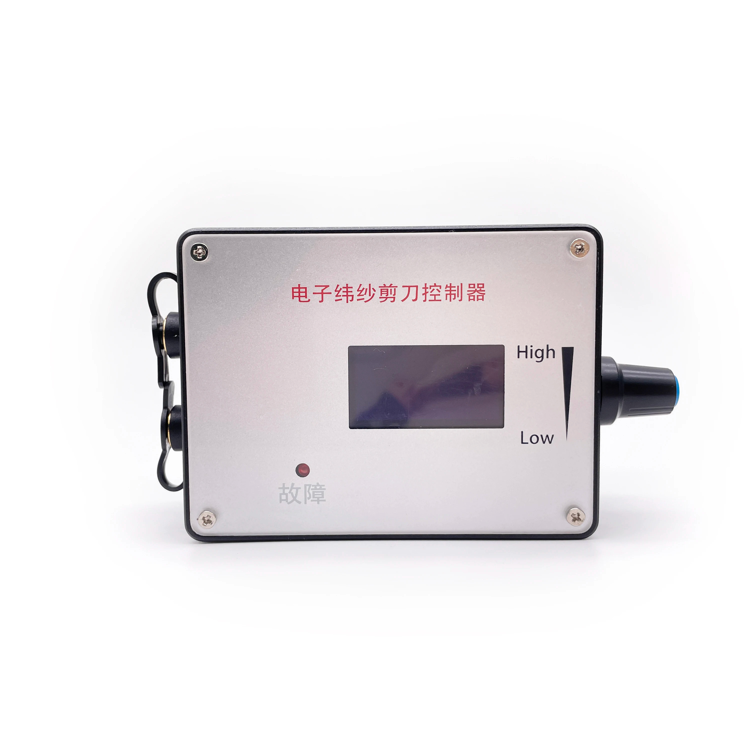
What is the working voltage and rated current of the governor?
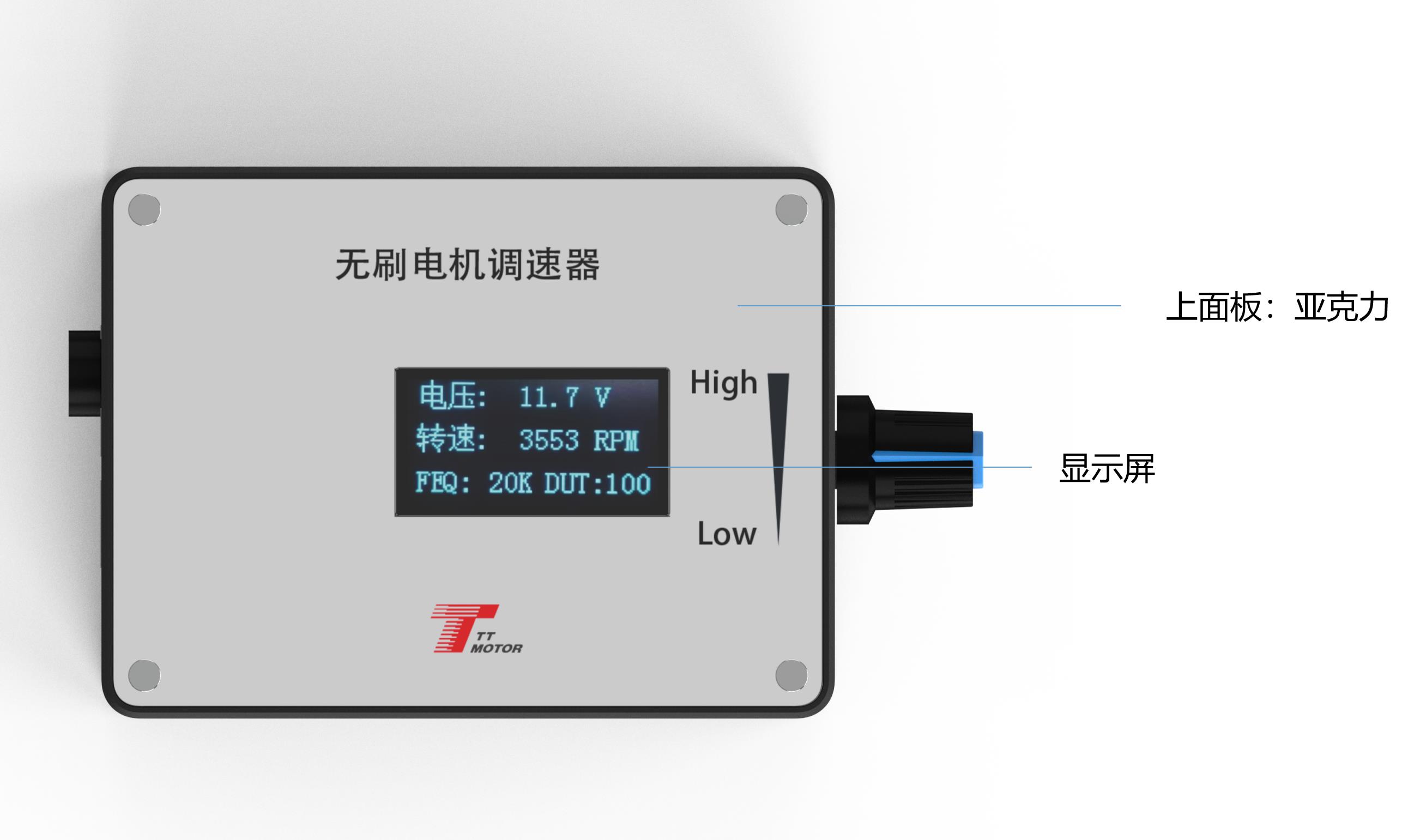
The input voltage range is DC5V-28V, and the rated current is MAX2A. For motors requiring larger currents, the motor power line should be connected directly to the power supply instead of passing through the governor board.
How do I adjust the output signal changes for ports 5 to 9?
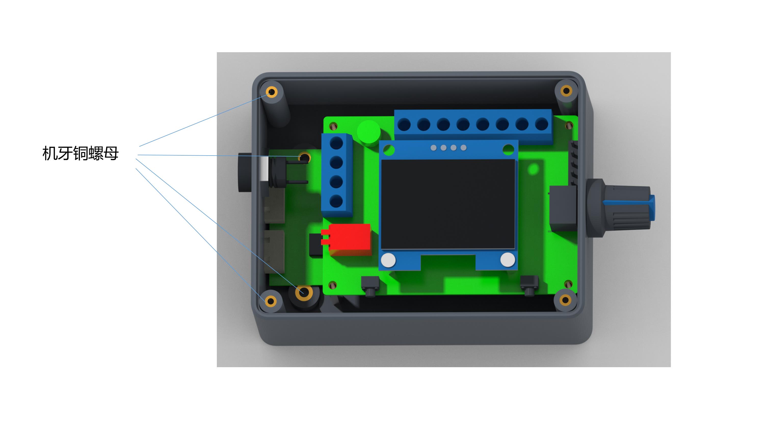
The output signal changes of the three control interfaces are adjusted using the onboard potentiometer.
How do I change the PWM frequency settings?
Press and hold touch switch 1 before powering on, then turn on the power. Release the button when the screen displays "FEQ:20K". Press switch 1 to decrease the value and switch 2 to increase it. The factory default setting is 20KHz.
How do I configure the motor pole number setting?
Hold down both touch switch 1 and touch switch 2 simultaneously before power-on, then power the board. Release the buttons once the screen displays "number of poles: 1 polarity". Use switch 1 to decrease and switch 2 to increase the pole count. The factory default is 1 pole.
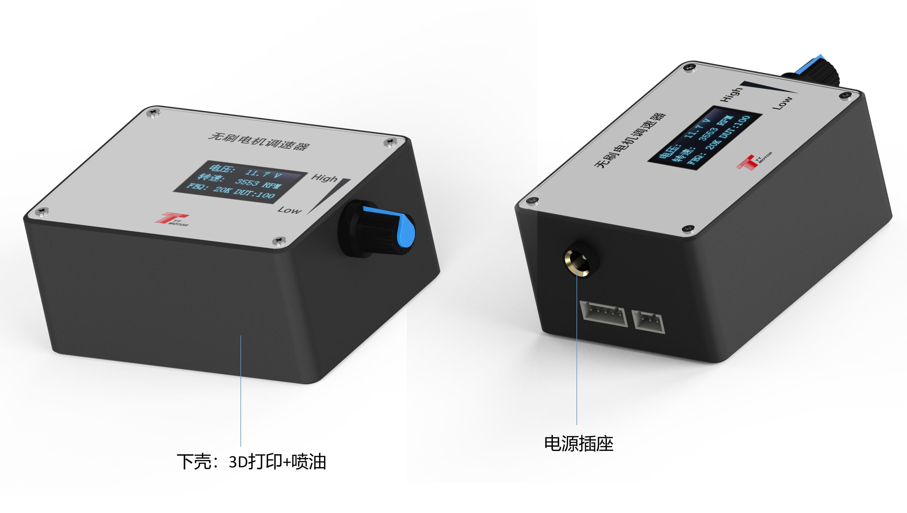
What is the purpose of the FG/FG*3 jumper cap?
It sets the feedback multiplier of the motor. Not adding the jumper cap defaults to a single times FG, while adding the jumper cap sets it to 3 times FG*3. Adjust this based on your actual motor's feedback requirements.
What are the critical wiring rules to prevent damage to the governor?
First, the positive and negative power supply inputs must be connected correctly and never reversed to avoid burning the unit. Second, do not apply a voltage exceeding 5V to the control ports ⑤ through ⑨.
 RACB Motor